CONTEC
KT88-2400
Series
Digital Brain Activity Mapping
Operator’s Manual
CONTEC
Web. http://www.contecmed.com.cn Email contec@contecmed.com.cn
This document contains confidential information that belongs to Contec Medical Systems Co., Ltd. No part of this document may be transmitted, reproduced, used or disclosed outside of the receiving organization without the express written consent of Contec Medical Systems Co., Ltd.
Copyright and Trademark Notices
This document contains information that is protected by copyright. All rights are reserved. No part of this document may be photocopied, reproduced or translated to another language without prior written consent of Contec Medical Systems Co., Ltd. The information contained in this document is subject to change without notice.
Responsibility of the User
l KT88-2400 digital
brain electric activity mapping should be used by the physicians who have
received professional training.
l The user should
read this operational manual carefully before operating KT88-2400, and operate
it in accordance with the manual.
l The user should
observe KT88-2400 and the patient when operating it.
l The user is
responsible to supply the use situations of KT88-2400 to Contec Medical Systems
Co., Ltd.
Responsibility of Contec Medical Systems Co., Ltd
l Contec Medical
Systems Co., Ltd supplies the standard product to the user.
l Contc Medical
Systems Co., Ltd installs and debugs KT88-2400 and trains the physicians.
l KT88-2400 should
be repaired by Contec Medical Systems Co., Ltd.
l Contec Medical
Systems Co., Ltd should use original accessories to repair KT88-2400.
l Contec Medical
Systems Co., Ltd is responsible to answer the questions about KT88-2400 on
time.
Other Important Information
The information in this document is subject to change without notice.
Contec Medical Systems Co., Ltd makes no warranty of any kind with
regard to this material, including, but not limited to implied warranties of
merchant ability and fitness for a particular purpose. Contec Medical Systems
Co., Ltd assumes no responsibility for any errors of omissions that may appears
in this document. Contec Medical Systems Co., Ltd makes no commitment to update
nor to keep current the information contained in this
document.
Technical Support and Service
Following are telephone numbers and addresses for contracting our
technical support and service personnel.
Contec Medical Systems Co., Ltd
P.R.C.
066004
Tel: 086-0335-8508888
Fax: 086-0335-8508543
E-mail address: contec@contecmed.com.cn
Warranty Information
Your CONTEC Warranty
Contec Medical Systems Co., Ltd (hereinafter referred to as “ Contec”) hereby warrants that Contec products (hereinafter referred to as “Products”) shall be free from defects in material and workmanship under normal use, service and maintenance for the warranty period of such Product from Contec or an authorized distributor or representative of Contec Normal use, service and maintenance means operation and maintenance in accordance with appropriate instructions and/or information guides. This Warranty does not apply to the Products caused by any or all of the following circumstances or conditions:
l Freight damage;
l Part and/or
accessories of the Products not obtained from or approved by Contec;
l Misapplication,
misuse, abuse, and failure to follow the Product instruction sheets and/or
information guides;
l Accident, a
disaster affecting the Products;
l Alterations or
modifications to the Products not authorized by Contec;
l Other events
outside of Contec ’s reasonable control or not arising
under normal operating conditions.
THE REMEDY UNDER THIS WARRENTY IS LIMITED TO THE REPAIR OR REPLACEMENT
WITHOUT CHARGE FOR LABOR OR MATERIALS, OR ANY PRODUCTRS FOUND UPON EXAMINATION
BY CONTEC TO HAVE BEEN DEFECTIVE. This remedy shall be conditioned upon receipt
of notice by Contec of any alleged defects promptly after discovery thereof
within the warranty period. Contec ’s obligation under the foregoing warranty
will further be conditioned upon the assumption by the purchase of the Products
(ⅰ) of all carrier charges with respect to any
Products returned to Contec’s principal place or any other place as
specifically designated by Contec or an authorized distributor or
representative of Contec, and (ⅱ) all risks of loss in
transit. It is expressly agreed that the liability of Contec is limited and
that Contec does not function as an insurer. A purchase of a Product, by its
acceptance and purchase thereof, acknowledges and agrees that Contec is not
liable for loss, harm or damage due directly or indirectly to an occurrence or
consequence therefrom relating to the Products. If Contec should be found
liable to anyone under any theory (except the expressed warranty set forth
herein) for loss, harm or damage, the liability of Contec shall be limited to
the lesser of the actual loss, harm or damage, or the original purchase price
of the Product when sold.
EXCLUDED FROM THE LIMITED WARRANTY SET
EXCEPT AS SET FORTH HEREIN WITH RESPECT TO REIMBURSEMENT OF LABOR
CHAGES, A PURCHASE’S SOLE EXCLUSIVE REMEDY AGAINST CONTEC FOR CLAIMS RELATING
TO THE PRODUCTS FOR ANY AND ALL LOSSES AND DAMAGES RESULTING FROM FROM ANY
CAUSE SHALL BE THE REPAIR OR REPLACEMENT OF DEFECTIVE PRODUCTS TO THE EXTENT
THAT THE DEFECT IS NOTICE AND CONTEC IS NOTIFIED WITHIN THE WARRANTY PERIOD. IN
NO EVENT, INCLUDING THE CLAIM FOR NEGLIGENCE, SHALL CONTEC BE LIABLE FOR
INCIDENTAL, SPECIAL OR CONSEQUENTIAL DAMAGES, OR FOR ANY OTHER LOSS, DAMAGE OR
EXPENSE OF ANY KIND, INCLUDING LOSS OF PROFITS, WHETHER UNDER TORT, NEGLIGENCE
OR ATRICT LIABILITY THEORIES OF LAW, OR OTHERWISE. THIS WARRANTY IS EXPRESSLY
IN LIEU OF ANY OTHER WARRANTIES, EXPRESS OR IMPLIED, INCLUDING, BUT NOT LIMITED
TO THE IMPLIED WARRANTY OF MERCHANT ABILITY AND THE WARRANTY OF FITNESS FOR A
PARTICULAR PURPPOSE.
Preface
This operation manual introduces you the total function of the KT88-2400 digital brain electric activity mapping and the detail operation procedure.
Please read the manual carefully before use the machine, which makes you easier to use it.
Table of Contents
Introduction
The feature of KT88-2400
The main technical index
Operational regulations
The place of electrode
The system operation
The print
The case to be taken out
The case-store management
Drop out the system
Notice
The notice for installation
The notice for application
The notice for protection
Maintenance and repair
Appendix
Digital brain electric activity mapping
The clinic application of digital brain electric activity mapping
Introduction
The features of digital brain electric activity mapping:
The digital brain electric activity mapping transit head bioelectrical activity into marked intuitionistic image, it becomes an advanced, no wound technical instrument for skull sickness, quatitative analysis for head enginery. Characters for this equipment are as follows:
u Help to bulge and recognize EEG partial features.
u Recognize the subtle features which was easy to be ignored ago.
u Help to academic communication, especially for the amateurs.
u Evaluate the unusual conditions in the traditional EEG and the unexplained situations by eye measure.
The main technical index
1. Channels: 19 lead EEG, 1 lead ECG, 1 lead respiration
2. Same module restrain proportion >100dB
3. The input resistance: 10MQ
4. Lead chose: single channel, double channel, or at will
5. The voltage of the power: 220V±10%
6. The frequency of the power: 50Hz
7.
The environment: Temperature:
Humidity: <90%
This operation manual is used for KT88-2400 series digital brain electric activity mapping. Because of the different setup in every series of machines, this manual is accordance to the largest configuration.
The operation regulation
The place of electrode
This system use silver chloridize channel electrode, drip in brine liquor at 5% at work.. Wash down with clean water after use and airing everday. Cover it to avoid exposal to protect the chlorination on electrode.
Place the electrode according to international system electrode emplacement.
The system operation
Turn on the computer, it enter the KT88-2400 series digital brain electric activity mapping operational system automatically.
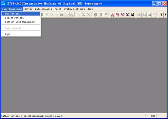
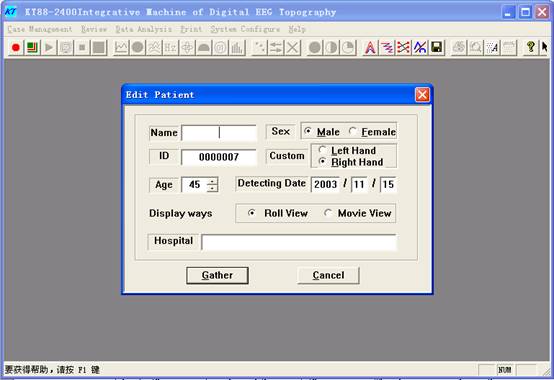
Click the “input new patient”; the physician input the parameters according to the patients’ condition. The name item could input English or Chinese. Press “Ctrl+Space” in keyboard would switch into Chinese input mode, and then input Chinese name. The physician can choose the acquired method (rolling screen display or constant display) by mouse’s arrowhead. Click “ready to acquire” and enter video setup.
The video setup
Click “prepare to acquire” and enter video setup. The physician can set up the quality, differentiate rate and other parameters of acquired picture.
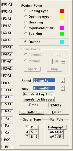
The acquisition control panel
In the acquisition interface, the left is the acquired wave to display the patient’s EEG at real time and the right is the acquisition control pannel to display various of premiums events and control the acquired methods.
Click ![]() button, the
physician could chose acquired velocity in practice.
button, the
physician could chose acquired velocity in practice.
Click ![]() button
,the physician could adjust the plus of EEG in practice.
button
,the physician could adjust the plus of EEG in practice.
Click ![]() button, the “work
frequency disturb” would get rid of AC work frequency disturb which is recommended
to use for batter images.
button, the “work
frequency disturb” would get rid of AC work frequency disturb which is recommended
to use for batter images.
Click ![]() button to determine
whether the contiguity of electrode and head, or the LBD would light if one of
them was in bad connection.
button to determine
whether the contiguity of electrode and head, or the LBD would light if one of
them was in bad connection.
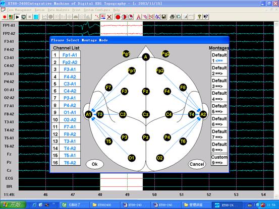
Click 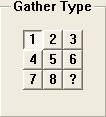 button to chose acquisition method according to practical use.
Click 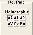 button
, the physician could chose reference electrode at will when gather EEG
according to practice.
button
, the physician could chose reference electrode at will when gather EEG
according to practice.
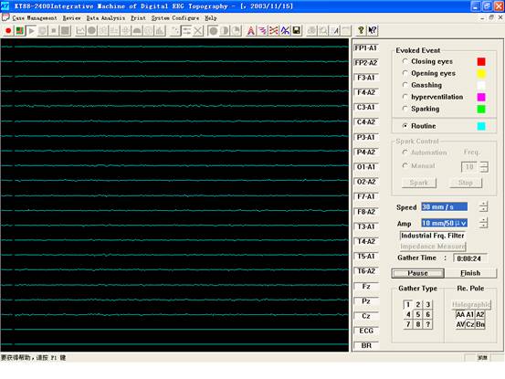
Click “end” to stop EEG acquisition.
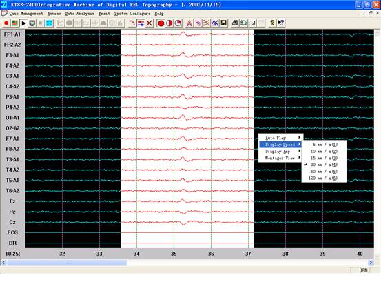
This menu is for user to replay EEG in secquence.
The physician can choose a segment of EEG to analyze. The method is as follow: remove the arrowhead of the mouse to the beginning of the EEG which is needed to analyze, and remove it to the end of that EEG. Press “SHIFT” on the keyboard, and Click the left key of the mouse, so as to choose the EEG segment.
The chosen EEG segment turns into white.
Remove the mouse to EEG, Click the right key of the mouse, and appear 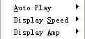 items. Move mouse to
“display velocity”, it changes to
items. Move mouse to
“display velocity”, it changes to 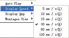 , The
physician could chose display speed in practice. Move mouse to “display plus”,
it changes to
, The
physician could chose display speed in practice. Move mouse to “display plus”,
it changes to 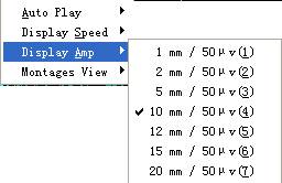 the physician could
chose display plus in practice. Move mouse to “play automatically”
the physician could
chose display plus in practice. Move mouse to “play automatically” 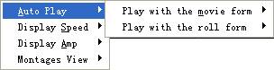 , and then the physician can choose to play EEG actually.
Finally, Click ![]() button to dispose the chosen EEG segment to FFT exchange and insert value
operation.
button to dispose the chosen EEG segment to FFT exchange and insert value
operation.
After the data disposal is over, the EEG is
to be analyzed. Click ![]() button enter menus as
follows:
button enter menus as
follows:
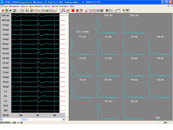
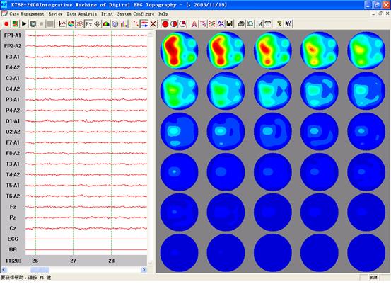
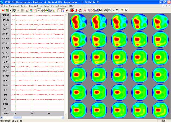
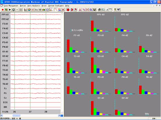
This menu is to observe power chart distributing map. Click left button of mouse on any power chart map could magnify this special lead power chart map.
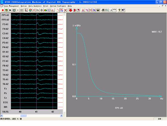
Click ![]() button as follows:
button as follows:
The left of this menu is to display the patient’s EEG, and the right is the look down relief map.
![]() button is used to switch
in the absolute relief map and
comparative relief map.
button is used to switch
in the absolute relief map and
comparative relief map.
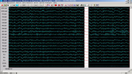
![]() button is used to
display 19-channel EEG in same screen.
button is used to
display 19-channel EEG in same screen.
![]() button is used to
display 11-channel EEG in same screen..
button is used to
display 11-channel EEG in same screen..
![]() button
is used to display 7-channel EEG in same screen.
button
is used to display 7-channel EEG in same screen.
Click
![]() button as follows:
button as follows:
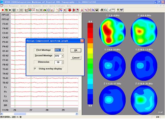
The physician can design compressed chart map according to menu tips:
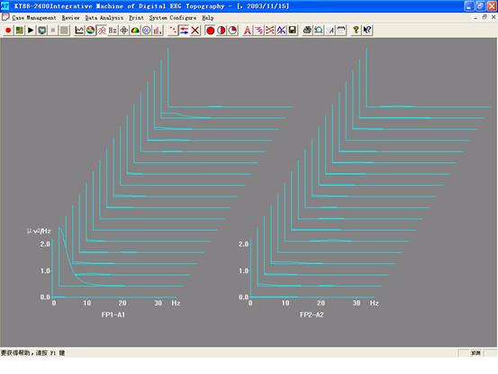
After the design is over, Click “OK” button as follows:
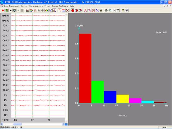
This menu is used to display compressed chart map of any two lead of the patient.
X means frequency , the unit is Hz.
Y means power, the unit is µ v2 /Hz.
Z means dimension of the compressed chart map , it can be decided by the physician
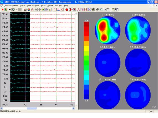
Click ![]() button , and enter the picture 9.
button , and enter the picture 9.
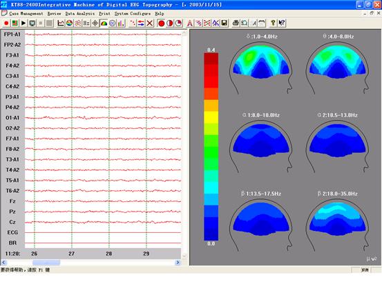
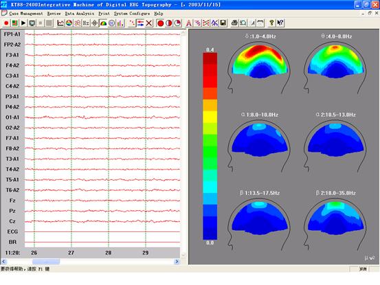
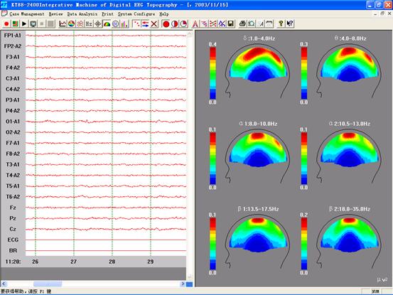
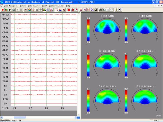
The left of this menu is the patient’s EEG. The right is the patient’s 1—30Hz relief map.
Click ![]() button to exchange absolute
EEG relief map and comparative EEG relief map.
button to exchange absolute
EEG relief map and comparative EEG relief map.
Click ![]() button , and enter the picture 10.
button , and enter the picture 10.
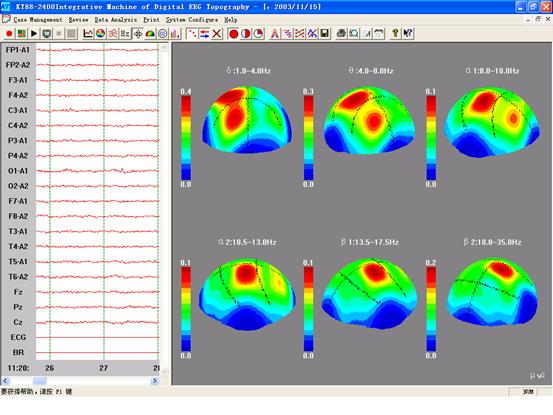
The right of the menu is the patient’s three-dimension stereoscopic EEG.
Press every EEG and turn it, which is easy for the physician to definite it.
Click ![]() to exchange absolute EEG and comparative EEG.
to exchange absolute EEG and comparative EEG.
Click
![]() button and enter picture 11.
button and enter picture 11.
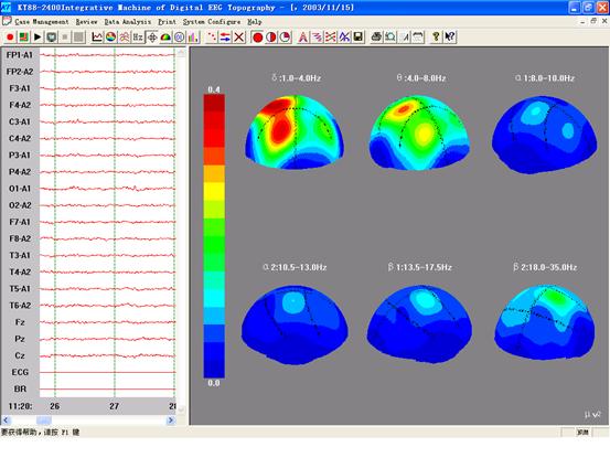
This menu is the patient’s side-view EEG.
Click ![]() button to observe the patient’s side-view EEG
from left or right.
button to observe the patient’s side-view EEG
from left or right.
Click ![]() button to exchange absolute EEG and
comparative EEG.
button to exchange absolute EEG and
comparative EEG.
This menu is patient’s power chart distributing map.
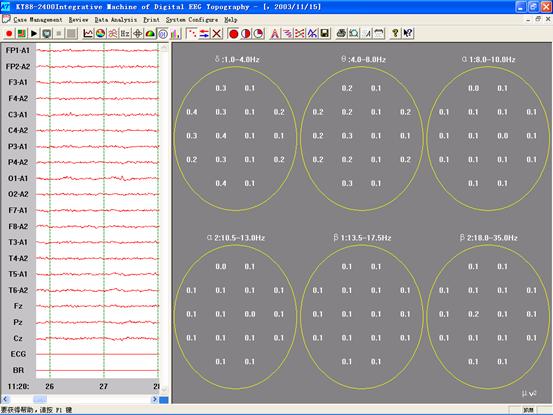
Click ![]() button to switch to power chart map. Click any
lead , you
could magnify it.
button to switch to power chart map. Click any
lead , you
could magnify it.
Click ![]() button and enter the picture 14.
button and enter the picture 14.
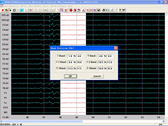
The physician could divide frequency
segment according to this menu. Click “OK” button to save and return or “Cancel”
button to cancel and return after partition. Click ![]() button after return and enter picture 15.
button after return and enter picture 15.
In this menu, the physician can choose the channel method.(monochannel or double-channel).
After the choice, Click “yes” and display the accordant EEG.
Click ![]() button and enter the picture 16..
button and enter the picture 16..
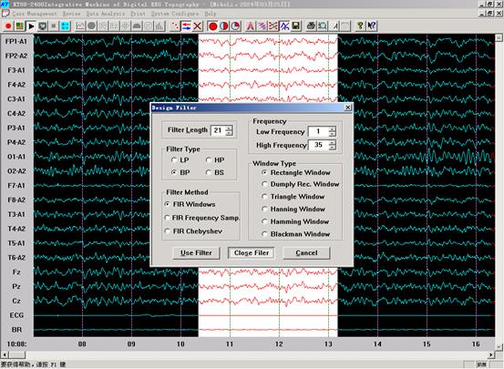
In this menu, the physician can design filter according to the patient’s EEG to clear EEG’s disturbance and false balance.
Click “OK” button and appear EEG which has being filtered.
Play
Click ![]() button in the
toolbar would play EEG from beginning to end automatically, and
button in the
toolbar would play EEG from beginning to end automatically, and ![]() button in the
toolbar to stop play.
button in the
toolbar to stop play.
Store the segment
You could chose the required segment by click the beginning of the EEG and click the end of the EEG, in the same time press “shift” on keyboard and press the left button of mouse. After choose EEG segment, Click the “store segment” in the “case management”.
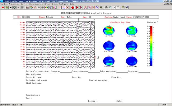
The physician could print the required
pictures in the No.4~No.13. Click ![]() button on any picture of them would get the
picture17,
button on any picture of them would get the
picture17,
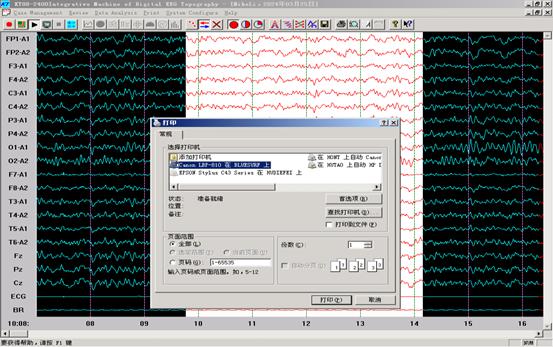 and Click “yes” to
print relief map or EEG. Click
and Click “yes” to
print relief map or EEG. Click ![]() to print report.
to print report.
Transfer the old case
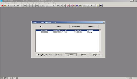
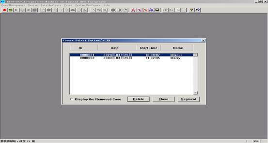
Click “take the old case out” and enter picture 19.
In this menu, choose the case which is needed to take out by the mouse. Then you would enter menus as follows: other operation just the same as “new patient”.
Case-store management
Click “case-store management” and enter picture 20.
In the picture19, the physician can delete the unnecessary cases by Clicking “Delete” on the keyboard. There would be a “*” before the case number which has being deleted. The deleted case couldn’t transfer any longer.
Logout the system
Click the ![]() button on the right of the menu to drop out
KT88-2400 series digital brain electric activity mapping system.
button on the right of the menu to drop out
KT88-2400 series digital brain electric activity mapping system.
Notice
The notice for installation
u Don’t hang anything on the power wire and be treaded by people.
u The machine needs good ground cable. The electric resistance isn’t more than 4 . don’t use the heat pipe or water pipe as the temporary ground cable.
u All the holes at the back of the machine should not be covered. Otherwise, the machine will be damaged because it’s too heat.
The notice for application
u The power voltage and frequency should be 220V and 50Hz.
u Don’t cover anything on the holes at the back of the machine.
u Don’t put the machine in a humid environment. When cleaning the machine, please take the plug away from the socket. Don’t use the liquid cleaner or the alcohol to wash it. Please use the wet cloth to wipe it. When the machine meets thunderstorm or it stays for a long time, make sure that the plug is taken away from the socket.
u The cables should be used in a correct way.
u In the cold winter, make the machine heat in advance and then use:
in the hot summer, don’t turn on the machine for a long time. For example, when
the temperature in the room is over
The notice for protection
u Don’t open the machine without authorization. The machine should be opened by the experienced technicians.
u Please take the plug away from the socket when meeting the following conditions:
l The power wire and the plug are broken.
l Something drops into the machine.
l The machine can’t work.
Maintenance and troubleshooting
|
Problem |
Cause |
Correction |
|
The power light isn’t light. |
1. The power plug isn’t put in the socket. |
Put the power plug in the socket. |
|
2. The power isn’t connected with the mainframe, or they’re not connected well. |
Connect the power wire with the mainframe tightly. |
|
|
3. The power is broken. |
Connect with the Technical department of Contec Medical Systems Co., Ltd |
|
|
The display light isn’t light. |
1. The display plug isn’t connected with the mainframe. |
Connect the display plug with the mainframe. |
|
2. The power of the display isn’t turned on. |
Turn on the power of the display. |
|
|
The display’s light is light but no display. |
1.The display’s wire isn’t connected with the mainframe. |
Connect the display’s wire with the mainframe. |
|
2.The light-control button is turned to the darkest. |
Adjust the light-control button. |
|
|
3.The display is broken. |
Connect with the technical department of Contec Medical Systems Co., Ltd |
|
|
The display’s light isn’t light and no display. |
The display is broken. |
Connect with the technical department of Contec Medical Systems Co., Ltd |
|
The printer isn’t printed. |
|
Read the related part of the operation manual. |
|
The print’s color is too light or not clear. |
The ink is used up. |
Change another new ink. |
|
The printer doesn’t work. |
1.The print line isn’t connected. |
Connect the print line tightly. |
|
2.The print line is broken. |
Change another new print line. |
|
|
3.The procedure of the print is wrong. |
Turn off the computer, and then turn on the printer, and the computer. |
|
|
EEG is disturbed a lot. |
1.The ground cable isn’t connected well. |
Place the ground cable in a standard way. |
|
2.The electrode is corroded. |
Change the new electrode. |
|
|
3.The cramp of the cable is corroded. |
Change the new cable. |
|
|
4.The cable is broken. |
Change the new cable. |
|
|
5.The hair is too dirty. |
Wash the hair. |
|
|
One part is disturbed a lot. |
The electrode of that place isn’t connected well. |
Wear the electrode again. |
|
Some channel is disturbed a lot. |
The electrode of that place isn’t connected well. |
Wear the electrode again. |
Appendix
The principle of EEG relief map
EEG relief map is a new method to analyze head bioelectricity in accordance with computer technology and computer picture disposal technology. As a new method around the world right now , it transforms huge complex but abnormity head bioelectricity to a form which could reflex quantitative change and orientation by computer. It displays complexion about diversification of head energy, it becomes an excellence , no wound and scientific method for skull sickness diagnose and research on head energy quantitative analysis. It is useful to analysis correctly on head energy using this technology .
Principle and method:
Placement of electrodes: lay 16 lead on outboard head according to international 10/20 system method standard, collect head wave signals and make A/D (modules transform) transform.
F-transform:
Transform the collected head wave signals to power chart map form to display the relationship about head wave frequency flied and power.
Frequency assort:
δfrequency flied: 0.8~3.8Hz
θ frequency flied: 4.0~7.8Hz
α1 frequency flied:
8.0~9.8Hz
α2 frequency flied:
10.0~12.8Hz
β1 frequency flied:
13.0~19.8Hz
β2 frequency flied:
20.0~29.8Hz
Insert value
operation:
Find out some insert function according to two-dimension
insert inside value principle based on these known sixteen number,
calculate 2500 point numbers. The expressions are as follows:
![]()
Print:
Print the
received data to module picture and get power relief picture.
Usual
relief map:
Some power of δ wave relief map
higher than regular value at 8 level and those exceed would belong to
abnormities.
Some power of θwave
relief map exceed normal value at 10 level local or whole head belong to
abnormities.
Evident un-symmetry
of αwave relief map about the distributing of the two
hemispheres.
Those exceed 3 or 5 belong to abnormities.
Power
chart relief map of patient:
Most of
the patient’s relief map would be abnormity and main of those are power exceed
of δwave and θwave, especially evident
in the forward of head. Followed by the increase of the power of α2wave (namelyαwave) and the power of βwave also has trend
to increase.